
Yamaguchi Framebuilding School - Day 10
The final day of framebuilding class, and so many things left to do! The last few days have been light on new concepts; lots of tube mitering, prep work, brazing, and filing. Now for something completely different! Today’s major tasks are precision machining of certain areas of the frame in order to transform a bicycle-shaped sculpture into an actual bicycle. Following that, we perform a careful alignment of the frame in order to ensure that the ride is true and balanced.
First, the seat tube is brought to final diameter using an adjustable reamer. Usually this is the sort of tool I would put in the tailstock of a lathe, but as is the theme, today it is hand cranked. It was necessary to use several passes of successively increasing size to clear the seat tube of scale and burrs.

Adjustable reamer used to bring the seat tube inner diameter to 27.3 mm.
The head tube of the frame is then reamed and faced in order to accept the headset bearings. Two tolerances need to be kept in mind here. The bearing seats must be of an accurate diameter for a light press fit (somewhere in the FN1 to FN2 range) and they must be precisely coaxial. If the upper and lower headset bearings are not aligned, a bending moment will be applied to the steering tube. This will result in rapid wear and premature failure of the headset bearings. To satisfy these geometric considerations, a line boring operation is performed. A single cutter simaltaneously reams the bearing seat to diameter and faces the end of the tube. The cutter is supported on a shaft which runs through the head tube, and is centered on the other bearing seat using a conical bushing. A heavy spring is used to clamp the assembly in place and provide cutting pressure. After one bearing seat is cut, the line boring rig is removed, flipped over, and used to cut the other seat.

Manual line boring assembly. From left to right: Handle, facing cutter, head tube, conical arbor, tension spring, nut.
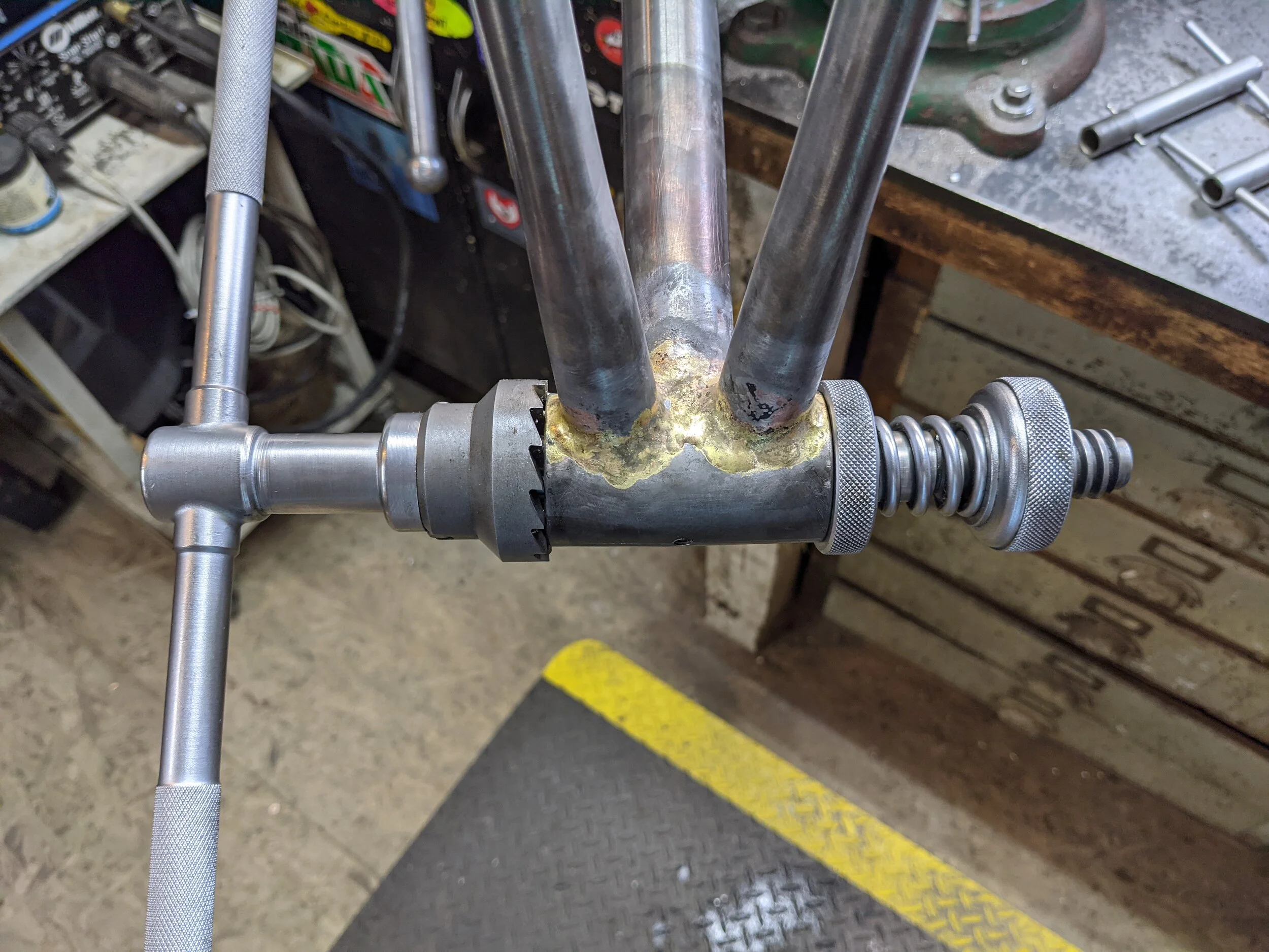
Just as the steering tube is supported by two bearings, so is the pedal crank axle in the bottom bracket. However, The bottom bracket bearings are not pressed directly into the tube. Instead, they are mounted in external bearing “cups” which are threaded in to the bottom bracket. therefore two precisely concentric sets of threads must be cut into opposite sides of the bottom bracket shell! This is accomplished by using a tool from the legendary Campagnolo framebuilder’s toolbox: two opposed threading cutters which slide along on a high-precision shaft. One of the cutters is left-hand threaded, which goes on the left-hand (or is that left foot?) side of the crank.

Campagnolo BB threading tool.

Cutting the BB threads. The cutters are alternately advanced by a few turns each.
Once the threads have been cut, the outer edge of the BB shell must be faced perpendicular to the axis defined by the threads. First, a clever split busing is threaded into both sides of the bottom bracket. The two halves of this bushing slide into each other with a precision fit, and they provide an accurate center axis for the bore. Another line boring tool, similar to the one used for facing the head tube, is threaded through the bushing, and both faces of the bottom bracket are machined true.

Two-part bottom bracket bushing.

Bottom bracket bushing once installed.
Facing using the bottom bracket shell using another line boring tool.
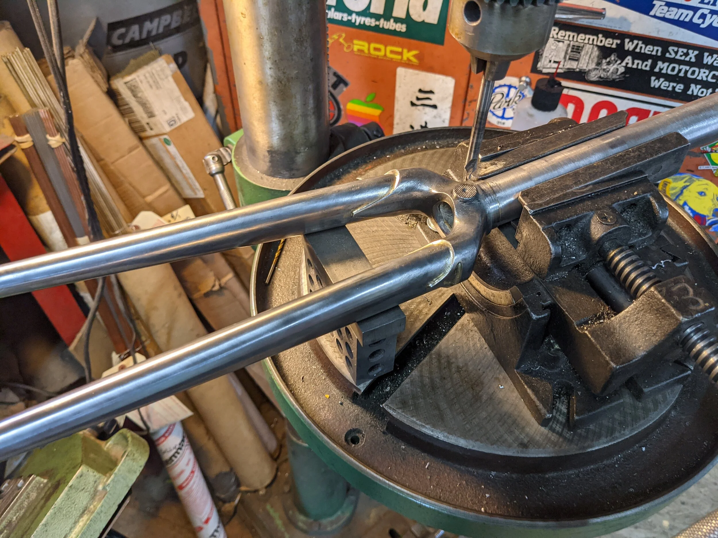
This concludes the machining of the frame, but the fork crown bearing race must also be machined. A single cutting tool is used to machine the boss, roughly cast onto the fork crown, into the bearing seat. The cutter is installed in a heavy iron tool body containing a collet which is lightly snugged onto the steering tube. This ensures that the crown bearing race is accurately centered on the steering tube axis. The contact pressure and torque on the cutter must be provided by the operator - and this step is exhausting! After this was done, it was time for lunch.

Machining the fork crown race. Maintaining contact pressure for such a large cutter was hard work!
After lunch, we turn to the other major task of the day; aligning the frame and fork. We begin by mounting the frame back on the flat assembly table. Now that the BB shell has been faced, the table’s clamping lug holds the shell perfectly vertical. We then use a dial indicator, to measure variations in the distance between the table top, and the top surface of each tube at various points. Since the tubes are straight cylinders, their top surfaces need to be a consistent distance from the table. The frame is manipulated by inserting long iron bars into the seatpost and headtube, and manually bending the frame. Since the frame is so stiff, quite a lot of force must be applied - this is a bit stressful on the one who did the welding! Once the front triangle is aligned, the rear triangle is likewise adjusted. A centering height gage is used to ensure that the dropouts for the rear wheel are the correct distance from each other, and centered on the center-line of the bike.

Frame mounted for alignment. The black object in the foreground is the centering tool used for the rear wheel dropouts.
After the frame is aligned, the fork gets the same treatment. The steering tube is clamped to a table, and the forks are manipulated until they are identical and symmetrical. The centering tool is used once again to make sure the front wheel drops are located correctly.

Fork mounted for alignment. Koichi is applying force using the adjustable cheater bar on the lower blade. The centering tool makes another appearance in the foreground, while the machinist’s square on the table makes sure the fork blades describe the same arc.
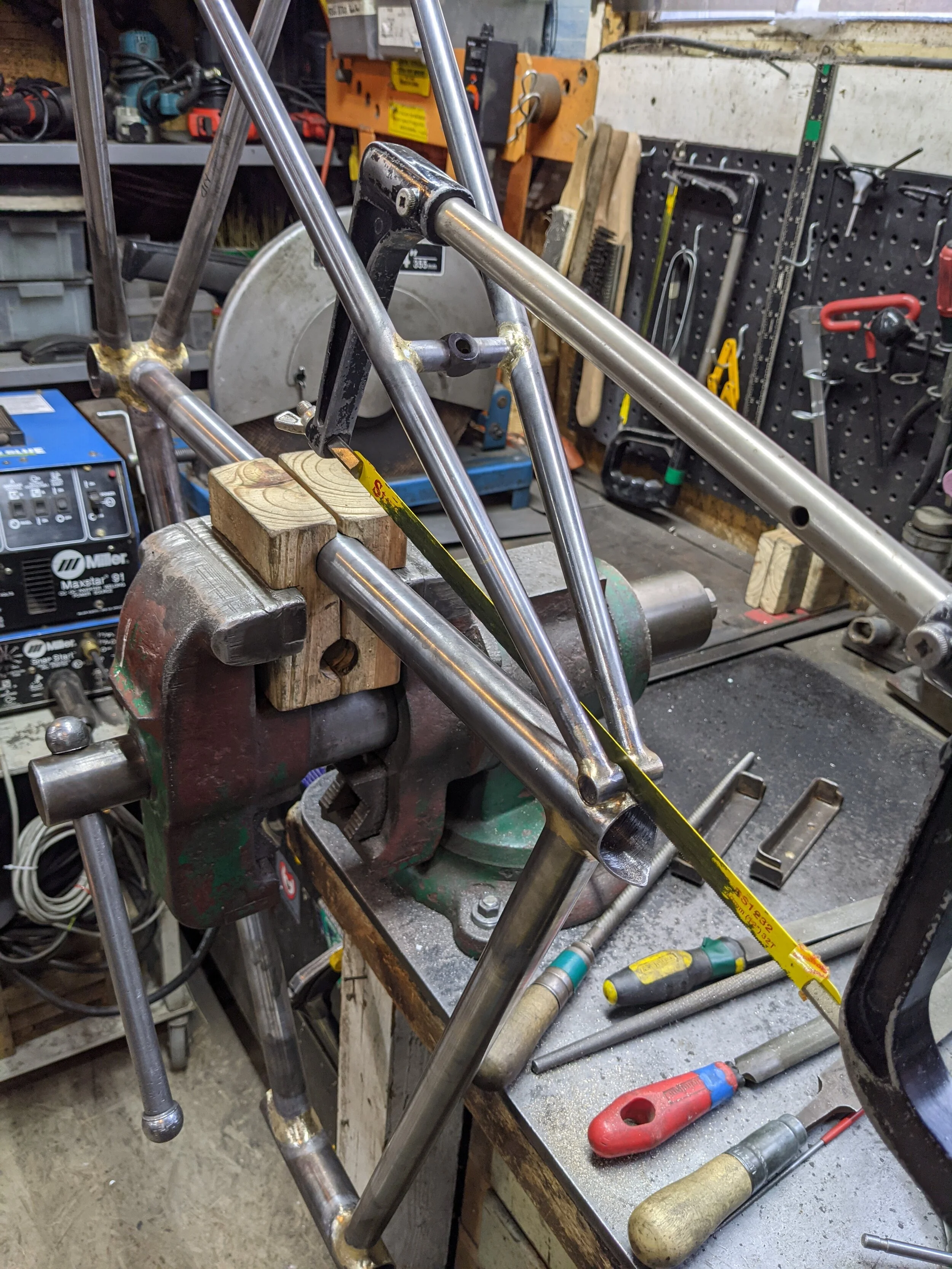
With the frame and fork aligned, all that’s left is a few minor machining operations. The front fork is drilled for the brake mount, and a slit is cut in the top of the seat tube to allow clamping of the seatpost. The stem is also slit to allow clamping on the handlebars and steering tube.

With all these steps complete, I have a few hours left for final smoothing and polishing. I still have a bit of “homework” to do before the frame is ready for paint, but it is complete and rideable! Time to buy some components and wheels, and take it out for a spin!
Koichi leaves me with some advice on finishing the bike, and tells me to send some photos and a ride report once it’s done. I also get a nice diploma and some sweet Yamaguchi merchandise! These two weeks have flown by at unbelievable speed, and I can hardly believe it’s over. Fortunately, this project still has a long way left to run!

Frame, fork and stem at the conclusion of the course.